English

Views: 0 Author: Site Editor Publish Time: 2026-08-10 Origin: Site


Unstable power supply threatens critical infrastructure constantly. It reduces equipment lifespan and causes costly, unplanned downtime. Facilities rely heavily on precise electrical control. You need a definitive diagnostic process. Determining if a component has failed matters immensely. You cannot afford to guess when managing electrical systems.
Accurate testing provides the vital baseline for your maintenance strategy. It drives the "repair versus replace" decision directly. This logical approach minimizes unnecessary capital expenditures. You will learn to recognize failure symptoms quickly. We explore the essential tools required for safe diagnostics. You will discover a step-by-step framework to verify component health.
Finally, we guide you through selecting the ideal replacement architecture. Upgrading a failed unit secures your operational stability. Let us examine how to isolate power issues and protect your valuable machinery.
Symptom Identification: Erratic voltage outputs, overcharging, or persistent voltage drops are primary indicators that a regulator requires immediate testing.
Diagnostic Method: A standard digital multimeter provides the definitive baseline for assessing regulator functionality under rest and load conditions.
Decision Criteria: Readings falling outside the manufacturer's specified operational range (commonly ±1% to ±5% of target voltage) confirm component failure.
Replacement Strategy: Failed units should be replaced based on specific application requirements, choosing between Single-Phase, Line Automatic, or APS architectures.
Voltage fluctuations cause severe degradation across your facility. Sensitive electronic components cannot tolerate continuous power shifting. These spikes generate excess thermal stress. This heat breaks down internal dielectrics prematurely. Such instability triggers unexpected system reboots. It disrupts your entire production workflow. Microprocessors lock up during voltage sags. Data corruption occurs frequently during unmitigated power surges. You lose valuable time restoring systems online.
You must actively look for observable markers. Ignoring early warning signs invites catastrophic failure. Watch for these common indicators:
Dimming or surging lighting circuits.
Battery banks exhibiting severe overcharging.
Protective relays tripping randomly during normal operation.
Unusual humming noises from distribution panels.
Equipment overheating despite adequate ventilation.
Running equipment on unverified power carries massive risk. A failing power component threatens your entire production line. Equipment replacement costs easily dwarf component replacement costs. You might lose a $50,000 CNC machine. You could fry a critical server rack. Acting quickly saves your capital budget. Diagnosing the issue early prevents cascading electrical failures. Preventative troubleshooting serves as an operational insurance policy.
Failure Symptom | Immediate Impact | System Risk Level |
|---|---|---|
Persistent Voltage Drops | Motors stall or run excessively hot. | High |
Erratic Spiking | Microprocessors reboot; data corrupts. | Critical |
Battery Overcharging | Electrolyte boils; thermal runaway occurs. | Critical |
Dimming Lights | Indicates poor load compensation. | Medium |
You need specific diagnostic equipment to proceed safely. A calibrated Digital Multimeter (DMM) serves as your primary tool. Do not rely on cheap, uncalibrated meters. They provide misleading readings. Secure high-quality, insulated test leads. You might also need a clamp meter for measuring current flow. Gather the manufacturer specifications for your specific machinery. You must know the exact target parameters before taking any measurements.
Follow critical safety measures strictly. Never compromise on electrical safety protocols. Execute Lockout/Tagout (LOTO) procedures flawlessly. You must wear proper Personal Protective Equipment (PPE). This includes insulated gloves and arc-flash face shields. Discharge all capacitors fully before touching any terminals. Capacitors store lethal energy long after system shutdown. Double-check zero energy states using your multimeter. Treat every circuit as live until verified dead.
Isolate outside variables to prevent false negatives. You must verify your battery health first. Check the alternator or generator output directly. Inspect your wiring integrity closely. Corroded terminals cause significant resistance. Loose grounding points mimic power failure symptoms perfectly. Confirm these foundational elements before blaming the regulation components. A thorough visual inspection saves hours of unnecessary troubleshooting.
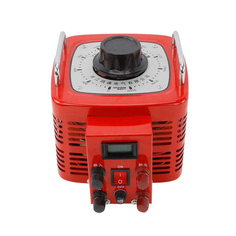
Measure the resting voltage across your power source initially. Keep the system completely powered down. Apply your multimeter leads to the primary output terminals. This reading establishes your control metric. You must understand the resting state first. For example, a standard 12V backup battery should read around 12.6V at rest. Document this baseline number carefully. It provides context for the subsequent dynamic tests.
Power on the system or generator carefully. Monitor the output at the main terminals. A healthy voltage regulator maintains a stable, tight range. Define this expected range based on your specific system specifications. Usually, the reading climbs slightly above the static baseline. It then locks into a steady number. Watch the multimeter display for several minutes. Note any slow drifting or sudden jumps. Consistency indicates proper internal circuitry operation.
Introduce a controlled electrical load to the system next. Activate large motors, heating elements, or computing banks. This forces the regulation circuit to work hard. The system must adapt to the sudden demand for current. Observe how the multimeter reading reacts. A temporary dip is normal. However, the system must recover almost instantly. Do not exceed the rated capacity during this load test.
Document the exact clamping speed and accuracy. You are judging the dynamic response quality here.
The unit should return power to the target parameter immediately.
Watch for erratic spiking above the target line.
Monitor for lagging recovery times.
Ensure the reading remains locked once the load stabilizes.
Delayed responses indicate severe internal component degradation. Erratic behavior proves the internal solid-state switching has failed.
Sometimes, the unit passes the test perfectly. If the reading holds steady within the specified threshold under load, it functions correctly. You must redirect your troubleshooting efforts elsewhere. Check the main distribution panels. Inspect the entire system for hidden grounding faults. Examine individual equipment power supplies. A passing grade means the central power stabilization works. Do not replace a functioning unit based on assumed symptoms.
Identify clear failure states quickly. The voltage might climb continuously as the unit warms up. This indicates a short circuit within the regulation board. It might drop catastrophically under load. This points to an open circuit or burned internal traces. You might see zero regulation altogether, delivering raw, dangerous power to your machinery. Any reading outside the manufacturer's ±1% to ±5% threshold confirms outright failure.
Modern solid-state regulation units are generally non-serviceable. Internal potting resin prevents component-level board repair. You cannot solder a new capacitor onto these enclosed boards easily. Failure necessitates outright replacement. This strategy guarantees long-term operational reliability. It also maintains essential safety compliance standards. Never attempt to patch a blown solid-state device. You risk causing severe fire hazards. Direct replacement remains the only viable engineering solution.
You might need a Single-Phase Voltage Regulator for targeted applications. Select this architecture for standard, isolated commercial loads. It offers excellent localized equipment protection. You install these units directly upstream of specific sensitive machines. They handle standard office environments perfectly. They also protect individual laboratory instruments from grid fluctuations. This provides cost-effective, decentralized power stabilization.
Consider a Line Automatic Voltage Regulator for comprehensive needs. It provides robust facility-wide power stabilization. It compensates for broader grid anomalies automatically. It handles heavy industrial load shifting easily. You deploy these at the main distribution feed. They protect multiple branch circuits simultaneously. Heavy manufacturing environments rely on this architecture. It prevents large motor startups from dropping power across the whole plant.
Advanced power applications require an APS Voltage Regulator. Frame this choice for highly precise, mission-critical tolerances. Modern IT infrastructure relies on absolute power consistency. Medical imaging equipment demands this extreme level of precision. APS units offer rapid switching and pure sine wave outputs. They eliminate micro-sags completely. Choose this when downtime or data loss presents unacceptable business risks.
Compare your options carefully before purchasing. Look closely at dynamic response time. Evaluate how the unit handles harmonic distortion. Assess future load scalability. Ensure seamless integration capabilities alongside your existing UPS systems. A mismatched architecture causes ongoing integration headaches.
Architecture Type | Ideal Application | Response Time | Scalability |
|---|---|---|---|
Single-Phase | Isolated commercial loads, specific machines. | Standard | Low (Decentralized) |
Line Automatic | Facility-wide stabilization, heavy industrial. | Fast | High (Centralized) |
APS | Mission-critical IT, medical equipment. | Ultra-Fast | Medium (Modular) |
Avoid mismatching current ratings during the selection process. Verify the exact phase configuration. Check the required response curves before buying. A mismatched replacement unit creates severe new hazards. Under-sizing the replacement leads to immediate thermal overload. Over-sizing can introduce inefficient power factors. Review your facility blueprints. Confirm the exact input and output parameters required by your specific machinery.
Professional installation remains non-negotiable. Hire certified electrical contractors. Ensure proper thermal management within the enclosure. Adequate heatsinking prevents premature component failure. Ensure clear airflow around the new chassis. Always conduct rigorous post-installation validation testing. Run the same baseline and load tests on the new unit. Verify it clamps power correctly before returning the system to full production.
Compile your facility load data today. Measure your peak demand periods accurately. Consult an electrical engineer to review your findings. Browse a specialized vendor catalog to match your specifications. Secure a certified replacement unit matched perfectly to your facility needs. Do not wait for a complete system collapse. Proactive replacement secures your operational future.
Standardized testing isolates power issues accurately and safely. Following a strict multimeter protocol prevents diagnostic guesswork. Upgrading a failing unit serves as high-ROI preventative maintenance. It protects your expensive downstream machinery from catastrophic damage. Take immediate diagnostic action today. Secure your baseline measurements and evaluate your system health. Contact a specialized vendor for precise replacement sizing. Protect your critical infrastructure before the next major power fluctuation hits.
A: Test the raw output of the generator first. Bypass the regulation stage entirely. If the generator produces the correct raw AC voltage, the generator works properly. The fault likely lies within the regulation circuit. If the raw output falls out of specification, the generator itself requires mechanical or electrical repair.
A: A standard digital multimeter provides only a snapshot in time. It often misses intermittent faults occurring randomly. For elusive issues, you need a data-logging multimeter or a power quality analyzer. These tools record electrical fluctuations over hours or days, capturing random spikes and drops perfectly.
A: The acceptable drop depends strictly on the manufacturer specifications. Generally, industrial standards allow a variance of ±1% to ±5% from the target parameter under full load. Anything exceeding this specified operational range strongly indicates internal degradation. It warrants immediate component replacement to prevent downstream damage.
A: Commercial units require annual preventative testing at a minimum. Facilities operating in harsh, dusty, or high-temperature environments should test biannually. Mission-critical environments like data centers often implement continuous automated monitoring. Regular manual load testing ensures optimal performance and prevents sudden operational failures.