English

Views: 0 Author: Site Editor Publish Time: 2026-08-03 Origin: Site


A transformer acts as the beating heart of any industrial or commercial facility. It safely bridges the gap between high-voltage utility lines and your daily operational equipment. Without it, modern electrical infrastructure simply cannot function.
Choosing the wrong unit often results in hidden energy losses, severe safety risks, and premature equipment failures. Engineers frequently overcompensate by heavily oversizing units. This drains long-term efficiency and significantly inflates upfront capital expenses. You must strictly balance your immediate load realities against environmental constraints and long-term performance.
This guide provides an objective framework to streamline your evaluation process. We will explore how to calculate accurate capacities, map exact utility voltages, and compare liquid-filled models against dry-type units. You will gain the actionable insights needed to finalize specifications confidently and efficiently.
Capacity calculation requires realism: Transformer sizing must balance continuous operational loads with future expansion buffers without falling into the trap of gross oversizing, which inflates no-load losses.
Environment dictates type: The choice between dry-type and liquid-filled units strictly depends on installation location (indoor vs. outdoor), fire safety codes, and maintenance capabilities.
Voltage matching is foundational: Precise mapping of primary utility supply to secondary load requirements, including phase and frequency, is a non-negotiable first step.
Total Cost of Ownership (TCO) outranks CapEx: Evaluating compliance with energy efficiency standards (e.g., DOE 2016) yields predictable long-term operational savings.
Every successful project begins by mapping exact electrical parameters. Your power distribution system relies on precise inputs to function safely. Establishing these baselines prevents catastrophic equipment failures and ensures smooth facility operations.
You must accurately map the incoming utility supply (primary voltage) to your facility equipment requirements (secondary voltage). Precise voltage matching stands as the most critical first step. An improper match can instantly destroy sensitive machinery or cause massive electrical fires. Always verify utility tap configurations before finalizing secondary voltage requirements.
Commercial and industrial environments rarely use identical phase configurations. You must determine whether your facility needs a single-phase or three-phase unit. Heavy motor loads, manufacturing belts, and large HVAC systems typically demand robust three-phase configurations. Additionally, you must match the frequency. North American grids operate at 60 Hz, while many international grids run at 50 Hz. Connecting incompatible frequencies leads to rapid overheating and core saturation.
Complex industrial setups often require multiple transformers operating in parallel. To achieve this safely, you must carefully specify the vector group (such as Dyn11). This dictates the winding arrangement and phase displacement. Furthermore, specifying the correct impedance percentage regulates fault current limits. Lower impedance allows higher fault currents. This demands heavier, more expensive downstream circuit breakers. Higher impedance restricts fault currents but increases voltage drops under heavy loads.
Modern facilities heavily utilize non-linear loads. Variable frequency drives (VFDs), server racks, and massive LED lighting arrays generate harmonic distortion. These harmonics bounce back into the electrical grid. They cause standard transformers to overheat rapidly. If your facility utilizes these technologies extensively, you need a K-factor rated unit. K-factor transformers feature specialized winding designs. They safely handle harmonic heat generation without derating overall capacity.
Proper transformer sizing requires a delicate balancing act. You must accommodate peak operational demands without wasting massive amounts of idle energy.
Calculating required capacity (kVA) relies on standardized electrical formulas. For a three-phase system, use this standard methodology:
Determine maximum load current in Amperes.
Identify the line-to-line secondary voltage.
Multiply Load Amps × Voltage × 1.732.
Divide the result by 1000 to find the base kVA.
This formula gives you the absolute minimum capacity required for full load operation.
Real-world operating conditions rarely mirror theoretical maximums. You must apply demand factors and diversity factors accurately. Continuous loads operate for three or more hours at maximum current. Non-continuous loads fluctuate. A hospital lighting system acts continuously. An industrial welding bay experiences intermittent spikes. Differentiating these helps you calculate a realistic thermal average. This prevents you from buying an unnecessarily massive unit.
Engineers frequently fall into a costly psychological trap. They drastically oversize equipment "just to be safe." This approach triggers a severe efficiency penalty. A grossly oversized unit carries higher upfront costs and demands a larger physical footprint. More importantly, it creates continuous core energy losses. The core remains energized 24/7. When you run a 2000 kVA unit to serve a 400 kVA load, you waste thousands of dollars annually in no-load iron losses.
While gross oversizing is detrimental, you still need room for growth. We recommend incorporating a practical 20–25% capacity buffer. This allowance safely absorbs expected facility expansions over the next decade. It achieves a sweet spot. You protect current operational efficiency while avoiding the massive costs of premature replacement.
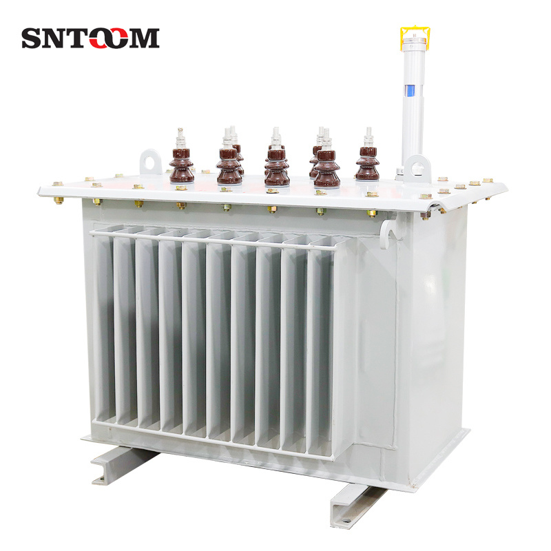
Your installation environment heavily dictates your equipment choice. You must evaluate physical location, fire codes, and maintenance access before selecting a category.
Dry-type units utilize air for cooling rather than specialized fluids. They typically feature cast resin or vacuum pressure impregnated (VPI) windings.
Best for: Commercial office buildings, hospitals, schools, and indoor manufacturing floors.
Evaluation Criteria: These units offer exceptionally high fire safety. They present zero fluid leak risks. This makes environmental compliance much easier. They also require significantly less preventative maintenance.
Trade-offs: They demand a larger physical footprint per kVA. They remain less tolerant to severe short-term overloads. Their overall lifespan is generally shorter compared to liquid-filled alternatives. They also generate more ambient heat into the surrounding electrical room.
Liquid-filled models submerge their core and windings in dielectric fluid. This fluid acts as both an insulator and a highly effective coolant.
Best for: Outdoor substations, heavy industrial plants, data centers, and high-voltage applications.
Evaluation Criteria: They provide superior cooling capacity and higher overall energy efficiency. They maintain a very compact footprint relative to their power output. They offer extreme durability in harsh weather conditions.
Trade-offs: They require robust spill containment systems. Stringent fire code setbacks often prevent close proximity to buildings. You must perform periodic fluid testing to monitor dissolved gases and dielectric strength. However, utilizing environmentally friendly dielectric fluids like ester oil can mitigate some fire and spill concerns.
Review the differences between the two primary categories below to guide your initial facility planning.
Feature Category | Dry-Type | Liquid-Filled |
|---|---|---|
Primary Location | Indoor environments | Outdoor environments |
Cooling Medium | Ambient air / Forced air fans | Mineral oil / Ester fluids |
Fire Risk Level | Very low | Moderate to High (requires mitigation) |
Footprint per kVA | Larger | Highly compact |
Overload Tolerance | Low | Excellent |
Maintenance Needs | Minimal (vacuuming dust) | Moderate (fluid sampling/testing) |
Initial purchase price represents only a fraction of true equipment costs. You must evaluate long-term energy consumption, material reliability, and strict regulatory standards to ensure a viable investment.
Mandatory energy efficiency standards reshape modern electrical design. In the United States, you must comply with DOE 2016 regulations. In Europe, Tier 2 standards dictate minimum efficiency levels. These frameworks force manufacturers to utilize better core steel and optimized winding geometries. Understanding these mandates ensures legal compliance. It also guarantees predictable long-term operational savings.
Evaluating operational efficiency requires understanding two distinct types of energy waste. No-load losses (core losses) remain constant whenever the unit is energized. The core steel constantly consumes energy to maintain the magnetic field, regardless of facility activity. Conversely, load losses (winding losses) vary directly with your facility's power consumption. They stem from the electrical resistance of the copper or aluminum coils. Balancing these two factors helps optimize your specific load profile.
Winding material directly impacts upfront cost, physical weight, and long-term conductivity. Copper offers superior electrical conductivity and mechanical strength. It allows for a smaller physical footprint. However, it carries a significant premium in upfront cost. Aluminum windings cost less and reduce the unit's overall weight. Yet, aluminum requires larger physical dimensions to match copper's capacity. Frame this decision around specific weight constraints and budget allocations rather than subjective preference.
Comparing two competitive quotes requires a comprehensive lifecycle analysis. Do not look solely at the invoice price. You must combine the initial purchase price with expected installation expenses. Next, calculate the projected 20-year energy losses based on the manufacturer's efficiency data. Finally, factor in scheduled maintenance routines. A cheaper, inefficient unit often costs thousands more over its operational life compared to a premium, high-efficiency model.
Mastering theoretical specifications is useless if the unit cannot physically fit inside your facility. Practical logistics heavily influence final Transformer Selection.
Always verify dimensional limits before approving a design. Will the unit fit through the electrical room doors? Can the facility floors support the immense weight? You must factor in rigging and hoisting requirements for multi-story installations. Indoor units also require substantial ventilation clearances. Blocking airflow pathways leads to immediate overheating and rapid insulation degradation.
Electrical equipment generates continuous hums through a process called magnetostriction. Evaluating acoustic noise restrictions proves critical. High sound levels disrupt office buildings, hospitals, or residential-adjacent commercial properties. Check NEMA ST 20 or IEEE standards for maximum allowable decibel ratings. You may need to specify specialized dampening pads or lower core flux densities to meet strict local noise ordinances.
The current global supply chain dictates realistic project timelines. Prolonged procurement timelines remain a harsh reality for custom-engineered electrical units. Standard off-the-shelf models might arrive in weeks. Custom configurations can require 30 to 50 weeks for delivery. Acknowledge these delays early. Plan your facility construction schedules and temporary power solutions accordingly.
Prepare a standardized list of specifications before approaching manufacturers or electrical contractors. Handing over clear, objective data ensures accurate and comparable quoting. Follow this essential checklist:
Capacity: Define your required kVA, including your 25% growth buffer.
Voltages: List exact primary utility feeds and secondary facility loads.
Configuration Phase: Confirm single-phase or three-phase operation.
Cooling Type: Specify dry-type or liquid-filled based on your location constraints.
Impedance & Enclosure: Note required impedance levels and NEMA enclosure ratings (e.g., NEMA 3R for outdoor protection).
Effective equipment selection is fundamentally an exercise in balancing load accuracy, environmental realities, and mandatory efficiency standards. You must align primary voltage feeds meticulously while calculating a realistic kVA capacity. Overestimating leads to excessive energy waste, while underestimating risks sudden operational downtime. Whether you deploy an indoor dry-type unit or a rugged outdoor liquid-filled model, physical constraints and lead times will ultimately dictate your project flow.
Consulting with a certified electrical engineer or a trusted manufacturer remains the vital final step before executing procurement. Use objective lifecycle data to drive your final decision rather than chasing the lowest upfront price tag. We encourage you to download a standardized sizing specification sheet, review detailed product comparison charts, or contact an engineering team for a project-specific consultation today.
A: First, perform a formal load study to identify peak continuous and non-continuous current demands. Apply standard diversity factors. Use the three-phase formula: kVA = (Amps × Voltage × 1.732) / 1000. Finally, add a 20-25% capacity buffer to accommodate future facility expansion without sacrificing daily efficiency.
A: Commercial applications typically require indoor, dry-type units focusing on strict fire safety, low acoustic noise, and zero fluid leak risks. Industrial selection leans toward outdoor, liquid-filled models designed for massive high-voltage loads, severe weather durability, and superior cooling capabilities.
A: Voltage matching ensures the primary utility supply correctly steps down to match your facility's exact equipment ratings. Failing to match these parameters causes immediate catastrophic equipment damage, severe system inefficiency, and total incompatibility with the local electrical grid feeds.
A: Yes, but it requires strict compliance with local fire codes. You typically must construct a specialized, fire-rated concrete vault with robust spill containment systems. Using less-flammable dielectric fluids, like natural ester oils, can sometimes reduce these stringent vault and setback requirements.